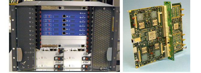
MCP Channel Unit Subsystem (CUS).
Square Peg Communications Inc.’s Multi-Channel Platform (MCP) is a hardware and software platform suitable for use in demanding satcom applications.
The MCP supports the implementation of Channel Unit Subsystems (CUSs) capable of supporting a variety of base station applications via a software-defined radio architecture. It conforms to industry standards for physical, electrical, and protocol interfaces to facilitate integration with other elements of the base station. It allows redundancy to be implemented efficiently where high availability is required.
The MCP also supports the implementation of physical layer testers, which are used to verify the performance of communications equipment intended for use in specific networks. A physical layer tester typically combines the transmit and receive capabilities of base stations and terminals with signal measurement functions and test automation facilities.
The architecture of the MCP is based on the use of a common LAN protocol for communication both within an MCP chassis and with other system elements. This provides a high degree of flexibility in configuring the system. For example, in addition to Channel Units, a CUS implemented with the MCP can include interfaces to terrestrial networks (e.g., T1/E1), as well as host processors to perform station management, network control, and call processing functions. The cards comprising a system can be distributed among multiple synchronized MCP chassis. All elements can be redundant for fault tolerance and high availability.
MCP-based Channel Unit Subsystems provide the modems for the Inmarsat-4 Classic Aero Ground Earth Stations (GESs) and BGAN Micro-Satellite Access Stations (Micro-SASs).

![]() High availability
High availability
![]() Hot swappable elements
Hot swappable elements
![]() Scaleable signal processing capability
Scaleable signal processing capability
![]() Ease of maintenance
Ease of maintenance
![]() Scaleable number of channels
Scaleable number of channels
![]() Scaleable signal processing capability
Scaleable signal processing capability
![]() Flexible IF interfacing
Flexible IF interfacing
![]() Flexible baseband interfacing
Flexible baseband interfacing
![]() High density
High density
![]() Excellent RF performance
Excellent RF performance
Channel Unit Subsystem |
|
|---|---|
| Enclosure | 19” / 7U PICMG® 2.16, rack mount (4U, 12U also available) |
| Cooling | Front to back |
| Power supplies | N+1, AC or DC |
| Shelf managers |
|
| Ethernet switches | Dual redundant 10/100 or Gigabit |
| Channel Units | 1 to 6 front / rear card pairs |
Channel Unit Front Card |
|
| Composite channels | 4 Tx/Rx (independently tuneable) |
| Composite channel bandwidth | Application-dependent, up to 1.25 MHz |
| Bearer channels per composite channel | Application-dependent; e.g., 4 for BGAN or Classic Aero |
| DSPs per composite channel | 1 x 500 / 600 MHz TigerSHARC or 2 x 500 MHz TigerSHARC |
| FPGA | Xilinx Virtex 4 FX60 |
| DSP / FPGA communications | 1 full duplex link port @ 800 Mbps 2 full duplex link ports @ 200 Mbps |
| DSP expansion | 1 expansion connector per DSP cluster for off-board FPGA co-processor |
| Control processor | PPC405 |
| Ethernet interface | 10/100/1000BaseT Auto-switching between Switch A, Switch B and front panel |
Channel Unit Rear Card |
|
| Number of IF feeds | 2 Tx + 2 Rx On-card loopback for self-test |
| Tx/Rx IF frequency range | 50 to 90 MHz |
| Max. total power per Tx feed | –17 dBm |
| Max. per-carrier Tx power | Dependent upon number of bearers per composite channel, typically –29 dBm |
| Tx phase noise density | @ 100 Hz: ≤ –70 dBc/Hz @ 1 kHz: ≤ –80 dBc/Hz @ 10 kHz: ≤ –90 dBc/Hz @ 100 kHz: ≤ –100 dBc/Hz |
| Tx spurious | < –86 dBm for carrier at –29 dBm |
| Tx 3rd order intermodulation | < –55 dBc (2 carriers at –20 dBm) |
| Tx I/Q imbalances | Negligible |
| Typical Rx dynamic range | –65 to –25 dBm –10 dBm max total |
| Reference input | 10 MHz |
4017 Carling Avenue, Suite 200
Ottawa, ON, Canada K2K 2A3
Tel + 1 613 271 0044
Fax+ 1 613 271 3007