
![]() IF to Ethernet high availability modem
IF to Ethernet high availability modem
![]() Ease of maintenance
Ease of maintenance
![]() Software reconfigurable
Software reconfigurable
![]() Utilizes floating point processors providing up to 3.6 GFLOPS or 14.4 GOPS per DSP
Utilizes floating point processors providing up to 3.6 GFLOPS or 14.4 GOPS per DSP
![]() Excellent RF performance
Excellent RF performance

RADIO LINK SIMULATORS
BGAN, FLEETBROADBAND, SWIFTBROADBAND
BGAN Physical Layer Tester (BPLT)
VOICE TESTERS
IsatData Pro Physical Layer Tester (DPLT)
AVIONICS SIMULATORS

Subsystems or complete hubs for satcom base stations requiring carrier-grade performance.

Square Peg Communications Inc.’s Multi-Channel Platform (MCP) is a hardware and software platform suitable for use in demanding satcom applications.
MCP Channel Units (CUs) are used to implement the physical layer of a variety of air interfaces via a software-defined radio architecture. They are intended for use in satellite or wireless base stations, signal measurement equipment, physical layer test equipment, channel simulators and other applications utilizing Digital Signal Processing (DSP).
A Channel Unit (CU) card set is comprised of a Channel Unit Front Card (CUFC) and a Channel Unit Rear Card (CURC). The CUFC is the DSP and FPGA based signal processing engine that implements the physical layer modulators and demodulators. The CUFC provides an Ethernet IP interface for control, status and data. It also incorporates an IPMI controller for shelf management in a suitably equipped chassis.
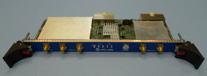
The CURC interfaces to the CUFC at digital complex baseband and provides the 70 MHz IF up and down conversion function. It provides two transmit IF output ports (TxA and TxB) and two receive IF input ports (RxA and RxB). Alternative IF or RF interfaces can be implemented by changing only the CURC.
Multiple CUs can be synchronized to an internally generated or externally provided timing pulse. High availability is facilitated by the use of redundant Ethernet connections, hot swap support and extensive built-in test. The CU firmware and configuration settings are field upgradeable via Ethernet.
The CU provides four transmit and four receive composite channels, each of which can be independently tuned within the IF band and output to or input from a selected IF feed. Within each composite channel, the number of bearers is dependent upon the signal bandwidth and the required processing power.
![]() IF to Ethernet high availability modem
IF to Ethernet high availability modem
![]() Ease of maintenance
Ease of maintenance
![]() Software reconfigurable
Software reconfigurable
![]() Utilizes floating point processors providing up to 3.6 GFLOPS or 14.4 GOPS per DSP
Utilizes floating point processors providing up to 3.6 GFLOPS or 14.4 GOPS per DSP
![]() Excellent RF performance
Excellent RF performance
Channel Unit Front Card | |
|---|---|
Form factor | 6U PICMG® 2.16 |
| Composite channels | 4 Tx/Rx (independently tuneable) |
| Composite channel bandwidth | Application-dependent, up to 1.25 MHz |
| Bearer channels per composite channel | Application-dependent; e.g., 4 for BGAN or Classic Aero |
| DSPs per composite channel | 1 x 500 / 600 MHz TigerSHARC or 2 x 500 MHz TigerSHARC |
| FPGA | Xilinx Virtex 4 FX60 |
| DSP / FPGA communications | 1 full duplex link port @ 800 Mbps 2 full duplex link ports @ 200 Mbps |
| DSP expansion | 1 expansion connector per DSP cluster for off-board FPGA co-processor |
| Control processor | PPC405 |
| Ethernet interface | 10/100/1000BaseT Auto-switching between Switch A, Switch B and front panel |
| IPMI interface | Per PICMG® 2.9 |
| On-card configuration | FPGA, DSP & PPC firmware Primary/secondary image select User configuration parameters |
| Indicators | 8 red/orange/green LEDs per composite channel 8 red/orange/green application- specific LEDs 1 blue hot swap LED |
| Power | Approx. 50W for 4 x 500 MHz DSPs + CURC with 2 Tx + 2 Rx |
Channel Unit Rear Card | |
|---|---|
Number of IF feeds | Up to 2 Tx + 2 Rx On-card loopback for self-test |
| Tx/Rx IF frequency range | 50 to 90 MHz |
| Max. total power per Tx feed | –17 dBm |
| Max. per-carrier Tx power | Dependent upon number of bearers per composite channel, typically –29 dBm |
| Tx phase noise density | @ 100 Hz: ≤ –70 dBc/Hz @ 1 kHz: ≤ –80 dBc/Hz @ 10 kHz: ≤ –90 dBc/Hz @ 100 kHz: ≤ –100 dBc/Hz |
| Tx spurious | < –86 dBm for carrier at –29 dBm |
| Tx 3rd order intermodulation | < –55 dBc (2 carriers at –20 dBm) |
| Tx I/Q imbalances | Negligible |
| Typical Rx dynamic range | –65 to –25 dBm –10 dBm max total |
| Reference input | 10 MHz @ 0 dBm |
| Timing sync input (optional) | 1 pps, TTL |
| On-card configuration | FPGA & PPC firmware Calibration data |
| Indicators | 2 red/orange/green LEDs per feed 1 blue hot swap LED |
| Power | Supplied by CUFC |